Amplifying Analog Voltages with the LM358
05.03.2025
Elektronik | Funk | Software
Der Technik-Blog
05.03.2025

25.02.2025
25.02.2025
12.02.2025

The MCP4822 is a dual-channel 12-bit digital-to-analog converter (DAC). Combined with an Arduino Uno or another microcontroller, the MCP4822 enables the conversion of digital signals into precise analog voltages. This blog article explains how to set up and operate the MCP4822 with an Arduino Uno.
The SPI interface (Serial Peripheral Interface) is a widely used protocol for fast and serial data communication between microcontrollers and peripheral devices or IC components like the MCP4822. Unlike other communication protocols such as I²C or UART, SPI operates on a master-slave principle, where one device (the master) controls the communication. The MCP4822 receives data from the microcontroller (Arduino) via this SPI interface. A 16-bit data word is transmitted, which contains the desired output value and configuration (e.g., channel selection). The MCP4822 is connected to the microcontroller as follows:
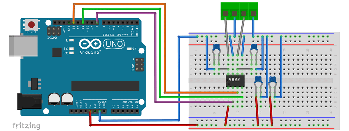
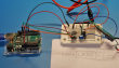
The MCP4822 connects to the Arduino via the SPI interface. The following connections are required for a functional circuit:
VCC and GND: The MCP4822 is connected to the 5V power supply of the Arduino via VCC (Pin 1). GND (Pin 7) is connected to the Arduino ground.
CS (Chip Select): Pin 2 of the MCP4822 is connected to a digital pin of the Arduino (Pin 8). This pin activates the MCP4822 for data transmission.
SCK (Serial Clock): Pin 3 of the MCP4822 is connected to the SPI clock pin of the Arduino (default: Pin 13).
SDI (Serial Data In): Pin 4 of the MCP4822 is connected to the MOSI pin of the Arduino (default: Pin 11). Digital data is transmitted here.
LDAC: Pin 5 can either be connected directly to GND for automatic updates of the analog outputs or connected to a digital pin of the Arduino for manual updates.
VOUTA and VOUTB: Pins 8 and 9 are the analog outputs of the MCP4822. They output the digitally transmitted voltage values.
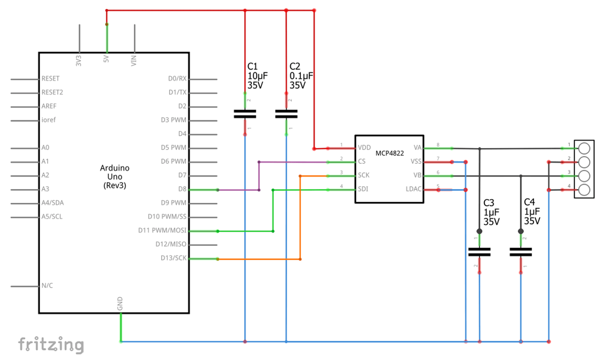
The schematic includes several capacitors recommended in the MCP4822 datasheet. These capacitors help to filter and stabilize the supply voltage and optimize the signal quality of the analog outputs. For a test setup on a breadboard, the capacitors can be omitted. However, small fluctuations or noise might occur, which could affect the analog output.
The program allows the MCP4822 to be controlled via the SPI interface of the Arduino. At startup, the SPI interface is initialized, and an initial value of 1250 (approx. 1.25V with 2x gain) is set on channel A of the MCP4822. Subsequently, voltage values between 0 and 4095 can be entered via the serial console and output at the analog channel. The setDACVoltage() function generates the 16-bit command word for the DAC and transmits it via SPI. No additional library is required, as SPI is already included with the Arduino IDE. The following example code can now be uploaded to the Arduino:
#include <SPI.h>

// More Information: https://www.aeq-web.com
// Pin configuration for Arduino -> MCP4822:
// | Pin 8 -> CS (Chip Select)   |
// | Pin 11 -> SCK (Serial Clock) |
// | Pin 13 -> SDI (Serial Data)  |
// | 5V     -> VDD                |
// | GND    -> VSS                |
// | GND    -> LDAC               |

int csPin = 8; // Chip Select Pin

void setup() {
  Serial.begin(9600); // Initialize serial communication for debugging
  pinMode(csPin, OUTPUT); // Configure CS pin as output
  digitalWrite(csPin, HIGH); // Set CS pin to HIGH (inactive)

  // Initialize SPI interface
  SPI.begin();
  delay(100);

  // Set initial voltage for channel A (example: 1250 corresponds to 1.2V at Gain = 2x)
  setDACVoltage(1250, 0);

  Serial.println("Enter a value between 0 and 4095 to change the output voltage at channel A!");
}

void loop() {
  // Check if there is input available from the serial monitor
  if (Serial.available() > 0) {
    String input = Serial.readStringUntil('\n'); // Read input until newline character

    // Convert input string to an integer
    int voltage = input.toInt();

    // Check if the input voltage is within the valid range (0 to 4095)
    if (voltage >= 0 && voltage <= 4095) {
      setDACVoltage(voltage, 0); // Set voltage on channel A
      Serial.print("Voltage set to: ");
      Serial.print(voltage);
      Serial.println(" mV");
    } else {
      Serial.println("Invalid input. Please enter a value between 0 and 4095.");
    }
  }
}


void setDACVoltage(uint16_t value, uint8_t channel) {
  if (value > 4095) value = 4095; // Limit value to 12-bit maximum

  // Create the 16-bit command word
  uint16_t command = 0;
  command |= (channel & 0x01) << 15; // Set channel (bit 15: 0 = A, 1 = B)
  command |= 0x1 << 12;              // Set active mode (bit 12)
  command |= (value & 0x0FFF);       // Set voltage value (12 bits)

  // Send the command via SPI
  digitalWrite(csPin, LOW); // Activate the DAC
  SPI.beginTransaction(SPISettings(1000000, MSBFIRST, SPI_MODE0));
  SPI.transfer16(command); // Transmit the 16-bit command
  SPI.endTransaction(); // End the SPI transaction
  digitalWrite(csPin, HIGH); // Deactivate the DAC
}

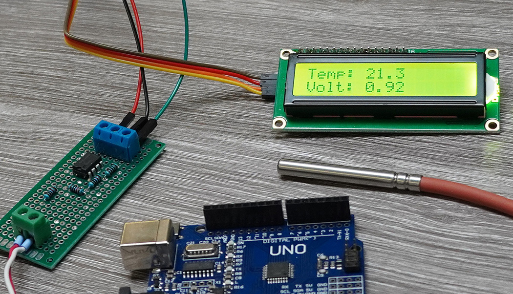
PT1000 sensors can not be measured directly analog with a microcontroller. How to build a PT100 Converter with LM358 and Arduino?
read more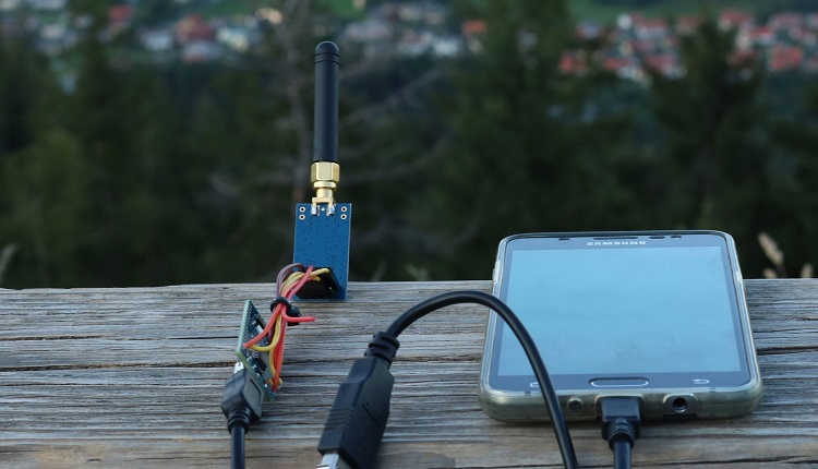
On this page we will show you how to make a data transfer with the CC1101 and an Arduino. Wiring plan and libraries are available on AEQ-WEB
read more
05.03.2025
25.02.2025
25.02.2025
12.02.2025
AEQ-WEB ist ein Blog von Alex & Andi, der sich mit Elektronik, Funk & Software beschäftigt
read moreAEQ-WEB © 2015-2026 All Right Reserved