Amplifying Analog Voltages with the LM358
05.03.2025
Elektronik | Funk | Software
Der Technik-Blog

05.03.2025

25.02.2025
25.02.2025

12.02.2025
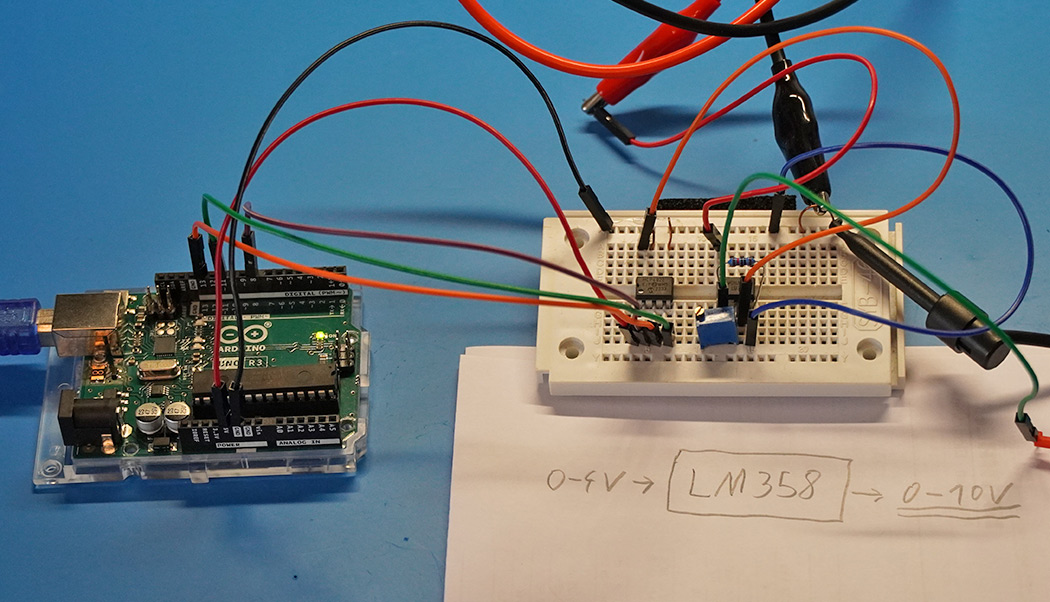
The LM358 is a widely used operational amplifier (op-amp) that is ideal for simple amplifier circuits. It is inexpensive, requires only a single supply voltage, and can amplify positive voltages without the need for an additional negative voltage. In many applications, particularly with digital-to-analog converters (DACs) like the MCP4822, low output voltages are generated, which are often insufficient for subsequent circuits. For example, the MCP4822 combined with an Arduino delivers a maximum output voltage of slightly over 4 volts, while many circuits require analog voltages in the range of 0 to 10 volts. This article explains how the LM358 can be used as an amplifier to increase an input voltage of 0 to 4 volts to an output voltage of 0 to 10 volts. The goal is to control this amplifier with an MCP4822 DAC to generate a programmable analog voltage in the range of 0 to 10 volts.
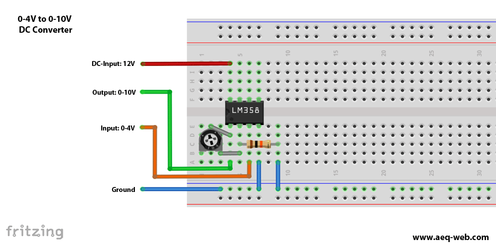
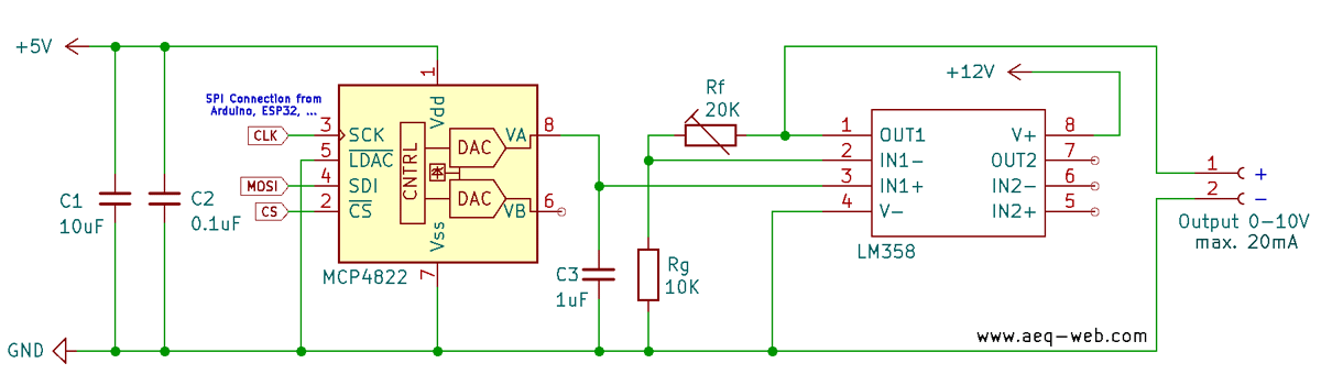
To amplify the voltage from 0–4V to 0–10V, an LM358 operational amplifier is used in a simple non-inverting amplifier configuration. The circuit requires a 12V power supply to achieve the desired output voltage. A 20 kΩ potentiometer is used as a variable resistor in the feedback loop, in combination with a 10 kΩ resistor between the inverting input and ground. This setup allows for a gain adjustment between 1x and 3x, enabling precise control of the output voltage. A 100nF capacitor between the supply voltage and ground helps with decoupling and stabilizes the circuit. Since the LM358 is not a rail-to-rail op-amp, the output voltage can reach approximately 11V with a 12V supply, rather than the full supply voltage. Additionally, the lower voltage limit is slightly above 0V, which should be considered in applications requiring precise output voltages.
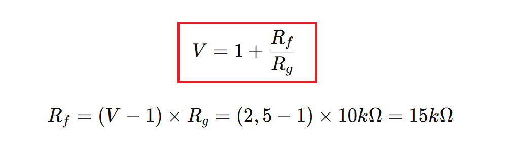
The gain of this circuit is calculated using the formula V = 1 + (Rf/Rg). By using a fixed resistor (Rf) instead of the potentiometer and rearranging the formula accordingly, the ideal value can be determined. To amplify 0–4V to 0–10V, the gain must be 2.5. If a 10 kΩ resistor is used for Rg, the ideal Rf is 15 kΩ.
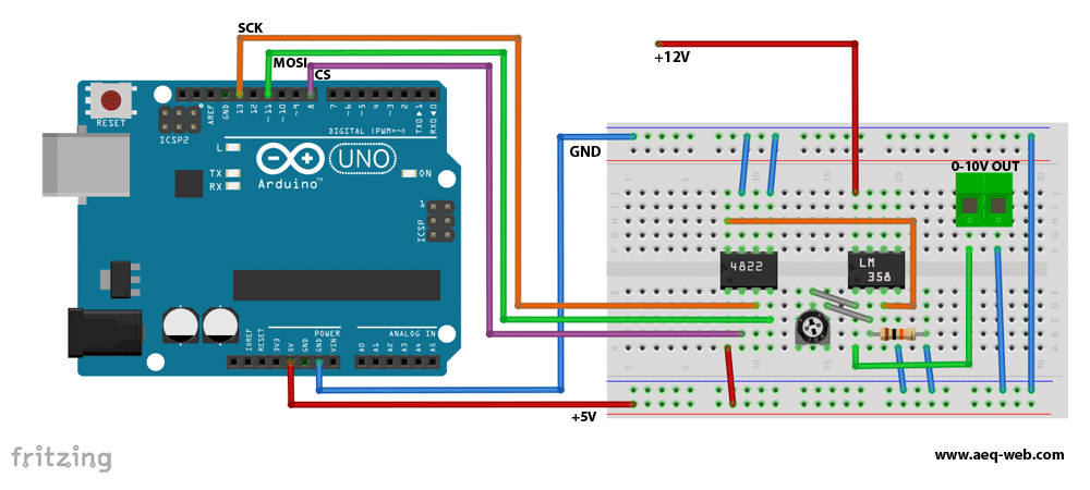
For flexible control of the output voltage, the amplifier circuit can be combined with a programmable digital-to-analog converter (DAC) and an Arduino. A DAC like the MCP4822 allows the generation of precise output voltages, which can then be amplified to the desired range by the LM358. The functionality and operation of the MCP4822 were already covered in a previous article. That article explains how to generate a programmable analog output voltage, which can then be adjusted to an extended voltage range using the amplifier circuit presented here.
The software also had to be modified and adapted to the operational amplifier. The following example code allows generating an analog voltage from 0 to 10V.
#include// More Information: https://www.aeq-web.com/analoge-spannung-verstaerken-mit-dem-lm385-opv-und-eine-analoge-spannung-von-0-10-volt-erzeugen-mit-arduino/ // // Pin configuration for Arduino -> MCP4822: // | Pin 8 -> CS (Chip Select) | // | Pin 13 -> SCK (Serial Clock) | // | Pin 11 -> SDI (Serial Data) | // | 5V -> VDD | // | GND -> VSS | // | GND -> LDAC | int csPin = 8; // Chip Select Pin float OpAmpFc = 2.5; //OpAmp amplification factor void setup() { Serial.begin(9600); // Initialize serial communication for debugging pinMode(csPin, OUTPUT); // Configure CS pin as output digitalWrite(csPin, HIGH); // Set CS pin to HIGH (inactive) // Initialize SPI interface SPI.begin(); delay(100); // Set initial voltage for channel A (example: 5000/2.5 = 2500mV set to ADC and gives 5V out after OpAmp LM358) int initVoltage = 5000; setDACVoltage(initVoltage/OpAmpFc, 0); // Set voltage on channel A Serial.println("Enter a value between 0 and 10000 to change the output voltage at channel A!"); } void loop() { // Check if there is input available from the serial monitor if (Serial.available() > 0) { String input = Serial.readStringUntil('\n'); // Read input until newline character // Convert input string to an integer int voltage = input.toInt(); // Check if the input voltage is within the valid range (0 to 10000) if (voltage >= 0 && voltage <= 10000) { int opvInput = voltage/OpAmpFc; setDACVoltage(opvInput, 0); // Set voltage on channel A Serial.print("Voltage set to: "); Serial.print(voltage); Serial.println(" mV"); } else { Serial.println("Invalid input. Please enter a value between 0 and 10000."); } } } void setDACVoltage(uint16_t value, uint8_t channel) { if (value > 4095){ value = 4095; // Limit value to 12-bit maximum } // Create the 16-bit command word uint16_t command = 0; command |= (channel & 0x01) << 15; // Set channel (bit 15: 0 = A, 1 = B) command |= 0x1 << 12; // Set active mode (bit 12) command |= (value & 0x0FFF); // Set voltage value (12 bits) // Send the command via SPI digitalWrite(csPin, LOW); // Activate the DAC SPI.beginTransaction(SPISettings(1000000, MSBFIRST, SPI_MODE0)); SPI.transfer16(command); // Transmit the 16-bit command SPI.endTransaction(); // End the SPI transaction digitalWrite(csPin, HIGH); // Deactivate the DAC }

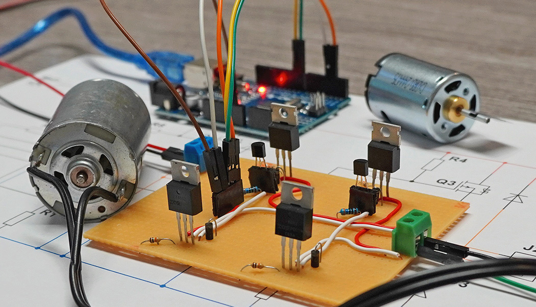
Control direction and speed of a DC-Motor with MOFETs on an Arduino. Four-quadrant operation
read more
The last article was about generating an analog voltage with the Arduino. The generated 0-4V can be amplified to 0-10V using the LM358 operational amplifier.
read more
05.03.2025
25.02.2025
25.02.2025
12.02.2025
AEQ-WEB ist ein Blog von Alex & Andi, der sich mit Elektronik, Funk & Software beschäftigt
read moreAEQ-WEB © 2015-2026 All Right Reserved