Amplifying Analog Voltages with the LM358
05.03.2025
Elektronik | Funk | Software
Der Technik-Blog

There is also a video on YouTube for this article: Standalone ATMega328 16x2 LCD Display control with 4-Bit in C - Amtel Studio (German)
In this article, we will show how to program an ATMega328 in Amtel Studio and how to load the software to the microcontroller via a programmer (AVRISP). As a simple example, we will control an LED on the PIN 15 (PORTB1). This requires an LED and one resistor of 220 ohms. The basic information about the microcontroller can be found here.
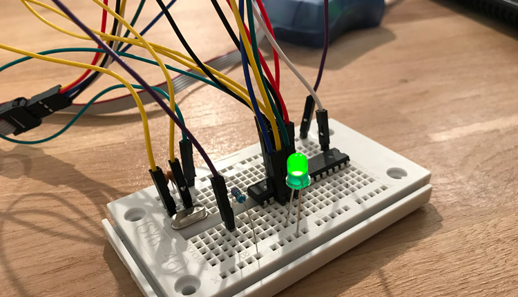
In this example, the ATMega328 is used on a breadboard. In addition to the 5V power supply, the programmer is also connected via ISP. In addition, we also use an external clock with 16 MHz. Pin 15 (PORTB1) is connected to the anode of the LED and the cathode is connected to ground with a 220 ohm resistor. When you programming the microcontroller for the first time, make sure that the bootloader is already burned.
If the hardware is completely connected, you can start with the development of the software. Therefore create a new porject in Amtel Studio. Choose project type "GCC C Executable Project" and define a name for your project. After clicking on "OK", a new window opens and ask you to select the correct microcontroller (ATMega328P or ATMega328). Then the necessary project files are generated. In the C-file (main.c) is already a part of the code, which can now be extended so that the LED flashes. The full code looks like this:
#define F_CPU 16000000UL
#include <avr/io.h>
#include <util/delay.h>

int main(void)
{
	DDRB |= (1<<DDB1);
    while (1)
    {
	PORTB |= (1<<PORTB1);
	_delay_ms(1000);
	PORTB &= ~ (1<<PORTB1);
	_delay_ms(1000);
    }
}First, the clock frequency must be defined (#define F_CPU 16000000UL). This corresponds to the frequency of the oscillator which in this example is 16MHz (16000000Hz). In the other two lines, two libraries must be integrated into the project. IIn the main program, pin 15 (PORTB 1) is defined as the first digital output. Then the rest of the code in the while loop is executed permanently. PORTB1 switches now on, then the controller wait one second before PORTB1 goes off again. Before PORTB1 is switched on again, the controller wait one second.
When the code is complete, you can start the project under "DEBUG". But first you have to define the connected Programmer, before you can continue your operation .During this process, the programmer flashes briefly and then the LED should start flashing. Amtel Studio tells you, when the build was successful.

In this article, we show how to control an LED with the ATMega328. Everything is programmed in Atmel Studio and we upload the Software via AVR ISP
read more
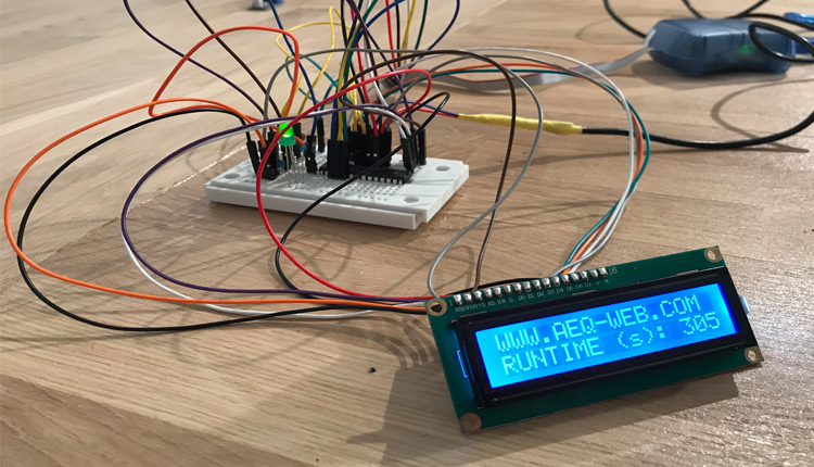
In this article we show how the ATMega328 drives a 16x2 character LC-Display with 4-bit. Everything is programmed in C with Amtel Studio and AVRISP Programmer
read moreAEQ-WEB © 2015-2026 All Right Reserved