Daly BMS Fernauslesen mit LoRaWAN
05.12.2025
Elektronik | Funk | Software
Der Technik-Blog

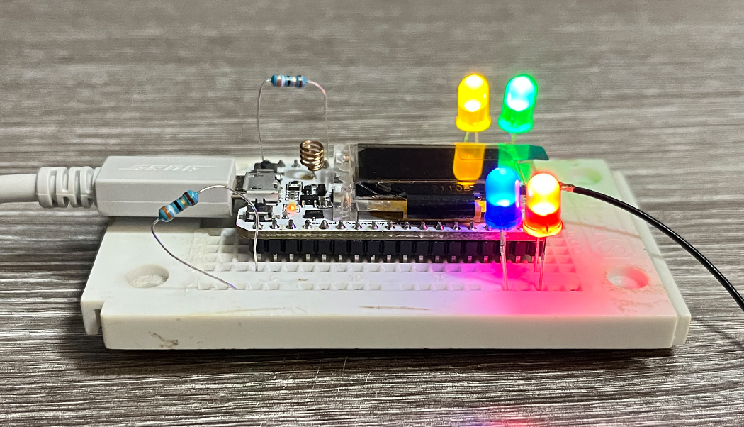
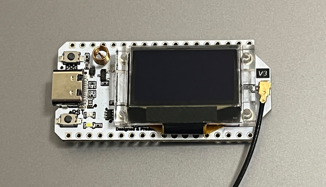
Bei diesem Beispielcode handelt es sich um eine modifizierte Version vom originalen OTTA-Beispielcode der LMIC-MCCI Library von CATENA. Das Pin-Mapping wurde für das Heltec ESP32 LoRa Board angepasst, jedoch sollte das Pin-Mapping vorher geprüft und entsprechend angepasst werden. Der Beispielcode steuert vier digitale Ausgänge des Mikrocontrollers, wenn eine korrekte Downlink-Message vom LoRaWAN Netzwerk empfangen wurde. Der Beispielcode sendet nach einem erfolgreichen JOIN in ein LORaWAN-Netzwerk im minütlichen Intervall einen "unconfirmed uplink" aus und arbeitet als LoRaWAN Class A Endgerät.
Achuntg: Das Pin-Mapping kann je nach Board Version unterschiedlich sein. Weitere Informationen dazu sind im Hauptartikel nachzulesen. Die Maximal zulässige Airtime sollte nicht überschritten werden!
/*******************************************************************************
   Copyright (c) 2015 Thomas Telkamp and Matthijs Kooijman
   Copyright (c) 2018 Terry Moore, MCCI

   Permission is hereby granted, free of charge, to anyone
   obtaining a copy of this document and accompanying files,
   to do whatever they want with them without any restriction,
   including, but not limited to, copying, modification and redistribution.
   NO WARRANTY OF ANY KIND IS PROVIDED.

   This example sends a valid LoRaWAN packet with payload "Hello,
   world!", using frequency and encryption settings matching those of
   the The Things Network.

   This uses OTAA (Over-the-air activation), where where a DevEUI and
   application key is configured, which are used in an over-the-air
   activation procedure where a DevAddr and session keys are
   assigned/generated for use with all further communication.

   Note: LoRaWAN per sub-band duty-cycle limitation is enforced (1% in
   g1, 0.1% in g2), but not the TTN fair usage policy (which is probably
   violated by this sketch when left running for longer)!
   To use this sketch, first register your application and device with
   the things network, to set or generate an AppEUI, DevEUI and AppKey.
   Multiple devices can use the same AppEUI, but each device has its own
   DevEUI and AppKey.

   Do not forget to define the radio type correctly in
   arduino-lmic/project_config/lmic_project_config.h or from your BOARDS.txt.

 *******************************************************************************/

#include <lmic.h>
#include <hal/hal.h>
#include <SPI.h>

//
// For normal use, we require that you edit the sketch to replace FILLMEIN
// with values assigned by the TTN console. However, for regression tests,
// we want to be able to compile these scripts. The regression tests define
// COMPILE_REGRESSION_TEST, and in that case we define FILLMEIN to a non-
// working but innocuous value.
//
#ifdef COMPILE_REGRESSION_TEST
# define FILLMEIN 0
#else
# warning "You must replace the values marked FILLMEIN with real values from the TTN control panel!"
# define FILLMEIN (#dont edit this, edit the lines that use FILLMEIN)
#endif

// This EUI must be in little-endian format, so least-significant-byte
// first. When copying an EUI from ttnctl output, this means to reverse
// the bytes. For TTN issued EUIs the last bytes should be 0xD5, 0xB3,
// 0x70.
static const u1_t PROGMEM APPEUI[8] = {FILLMEIN};
void os_getArtEui (u1_t* buf) {
  memcpy_P(buf, APPEUI, 8);
}

// This should also be in little endian format, see above.
static const u1_t PROGMEM DEVEUI[8] = {FILLMEIN};
void os_getDevEui (u1_t* buf) {
  memcpy_P(buf, DEVEUI, 8);
}

// This key should be in big endian format (or, since it is not really a
// number but a block of memory, endianness does not really apply). In
// practice, a key taken from ttnctl can be copied as-is.
static const u1_t PROGMEM APPKEY[16] = {FILLMEIN};
void os_getDevKey (u1_t* buf) {
  memcpy_P(buf, APPKEY, 16);
}

static uint8_t mydata[] = "0000";
static osjob_t sendjob;

bool join_success = false;

// Schedule TX every this many seconds (might become longer due to duty
// cycle limitations).
const unsigned TX_INTERVAL = 60;

int output_1 = 12;  //Output Pin 1
int output_2 = 13;  //Output Pin 2
int output_3 = 4;   //Output Pin 3
int output_4 = 16;  //Output Pin 4

bool output_1_state;
bool output_2_state;
bool output_3_state;
bool output_4_state;


// Pin mapping
const lmic_pinmap lmic_pins = { // Pins on Heltec ESP32 LoRa Board
  .nss = 18,
  .rxtx = LMIC_UNUSED_PIN,
  .rst = 14,
  .dio = {26, 34, 35},
};


void printHex2(unsigned v) {
  v &= 0xff;
  if (v < 16)
    Serial.print('0');
  Serial.print(v, HEX);
}

void onEvent (ev_t ev) {
  Serial.print(os_getTime());
  Serial.print(": ");
  switch (ev) {
    case EV_SCAN_TIMEOUT:
      Serial.println(F("EV_SCAN_TIMEOUT"));
      break;
    case EV_BEACON_FOUND:
      Serial.println(F("EV_BEACON_FOUND"));
      break;
    case EV_BEACON_MISSED:
      Serial.println(F("EV_BEACON_MISSED"));
      break;
    case EV_BEACON_TRACKED:
      Serial.println(F("EV_BEACON_TRACKED"));
      break;
    case EV_JOINING:
      Serial.println(F("EV_JOINING"));
      break;
    case EV_JOINED:
      Serial.println(F("EV_JOINED"));
      {
        u4_t netid = 0;
        devaddr_t devaddr = 0;
        u1_t nwkKey[16];
        u1_t artKey[16];
        LMIC_getSessionKeys(&netid, &devaddr, nwkKey, artKey);
        Serial.print("netid: ");
        Serial.println(netid, DEC);
        Serial.print("devaddr: ");
        Serial.println(devaddr, HEX);
        Serial.print("AppSKey: ");
        for (size_t i = 0; i < sizeof(artKey); ++i) {
          if (i != 0)
            Serial.print("-");
          printHex2(artKey[i]);
        }
        Serial.println("");
        Serial.print("NwkSKey: ");
        for (size_t i = 0; i < sizeof(nwkKey); ++i) {
          if (i != 0)
            Serial.print("-");
          printHex2(nwkKey[i]);
        }
        Serial.println();
      }
      // Disable link check validation (automatically enabled
      // during join, but because slow data rates change max TX
      // size, we don't use it in this example.
      LMIC_setLinkCheckMode(0);
      join_success = true;

      break;
    /*
      || This event is defined but not used in the code. No
      || point in wasting codespace on it.
      ||
      || case EV_RFU1:
      ||     Serial.println(F("EV_RFU1"));
      ||     break;
    */
    case EV_JOIN_FAILED:
      Serial.println(F("EV_JOIN_FAILED"));
      break;
    case EV_REJOIN_FAILED:
      Serial.println(F("EV_REJOIN_FAILED"));
      break;
    case EV_TXCOMPLETE:
      Serial.println(F("EV_TXCOMPLETE (includes waiting for RX windows)"));
      if (LMIC.txrxFlags & TXRX_ACK) {
        Serial.println(F("Received ack"));
      }

      if (LMIC.dataLen) {
        Serial.print(F("Received "));
        Serial.print(LMIC.dataLen);
        Serial.println(F(" bytes of payload"));

        //show downlink payload as HEX
        for (int i = LMIC.dataBeg; i < LMIC.dataBeg + LMIC.dataLen; i++) {
          Serial.print("Byte_");
          Serial.print(i);
          Serial.print("=");
          Serial.print(LMIC.frame[i], HEX);
          Serial.print("; ");
        }
        Serial.println();


        byte channel = LMIC.frame[LMIC.dataBeg]; //Downlink byte 0 - Output channel
        bool state = LMIC.frame[LMIC.dataBeg + 1]; //Downlink byte 1 - Output on/off

        switch_output(channel, state);
      }
      // Schedule next transmission
      os_setTimedCallback(&sendjob, os_getTime() + sec2osticks(TX_INTERVAL), do_send);
      break;
    case EV_LOST_TSYNC:
      Serial.println(F("EV_LOST_TSYNC"));
      break;
    case EV_RESET:
      Serial.println(F("EV_RESET"));
      break;
    case EV_RXCOMPLETE:
      // data received in ping slot
      Serial.println(F("EV_RXCOMPLETE"));
      break;
    case EV_LINK_DEAD:
      Serial.println(F("EV_LINK_DEAD"));
      break;
    case EV_LINK_ALIVE:
      Serial.println(F("EV_LINK_ALIVE"));
      break;
    /*
      || This event is defined but not used in the code. No
      || point in wasting codespace on it.
      ||
      || case EV_SCAN_FOUND:
      ||    Serial.println(F("EV_SCAN_FOUND"));
      ||    break;
    */
    case EV_TXSTART:
      Serial.println(F("EV_TXSTART"));
      break;
    case EV_TXCANCELED:
      Serial.println(F("EV_TXCANCELED"));
      break;
    case EV_RXSTART:
      /* do not print anything -- it wrecks timing */
      break;
    case EV_JOIN_TXCOMPLETE:
      Serial.println(F("EV_JOIN_TXCOMPLETE: no JoinAccept"));
      break;

    default:
      Serial.print(F("Unknown event: "));
      Serial.println((unsigned) ev);
      break;
  }
}

void do_send(osjob_t* j) {
  // Check if there is not a current TX/RX job running
  if (LMIC.opmode & OP_TXRXPEND) {
    Serial.println(F("OP_TXRXPEND, not sending"));
  } else {
    // Prepare upstream data transmission at the next possible time.

    mydata[0] = output_1_state; // Byte 0 = state of output 1
    mydata[1] = output_2_state; // Byte 1 = state of output 2
    mydata[2] = output_3_state; // Byte 2 = state of output 3
    mydata[3] = output_4_state; // Byte 3 = state of output 4

    LMIC_setTxData2(1, mydata, sizeof(mydata) - 1, 0);
    Serial.println(F("Packet queued"));
  }
  // Next TX is scheduled after TX_COMPLETE event.
}

void setup() {
  Serial.begin(9600);
  Serial.println(F("Starting"));
  SPI.begin(5, 19, 27, 18); // Pins on Heltec ESP32 LoRa Board

  pinMode(output_1, OUTPUT);
  pinMode(output_2, OUTPUT);
  pinMode(output_3, OUTPUT);
  pinMode(output_4, OUTPUT);

#ifdef VCC_ENABLE
  // For Pinoccio Scout boards
  pinMode(VCC_ENABLE, OUTPUT);
  digitalWrite(VCC_ENABLE, HIGH);
  delay(1000);
#endif

  // LMIC init
  os_init();
  // Reset the MAC state. Session and pending data transfers will be discarded.
  LMIC_reset();

  // Start job (sending automatically starts OTAA too)
  do_send(&sendjob);
}

void loop() {
  os_runloop_once();
}

void switch_output(int output, bool state) {

  switch (output) {
    case 1:  // Switch output 1
      digitalWrite(output_1, state);
      output_1_state = state;
      break;
    case 2:  // Switch output 2
      digitalWrite(output_2, state);
      output_2_state = state;
      break;
    case 3:  // Switch output 3
      digitalWrite(output_3, state);
      output_3_state = state;
      break;
    case 4:  // Switch output 4
      digitalWrite(output_4, state);
      output_4_state = state;
      break;
  }

  Serial.print("Output ");
  Serial.print(output);
  Serial.print(" switched ");
  if (state == true) {
    Serial.print("on");
  } else {
    Serial.print("off");
  }
  Serial.println("!");

}

Einstieg in das LoRaWAN (TTN) mit dem Heltec LoRa32 V3 und Einrichtung vom Board in der Arduino IDE
Weiterlesen
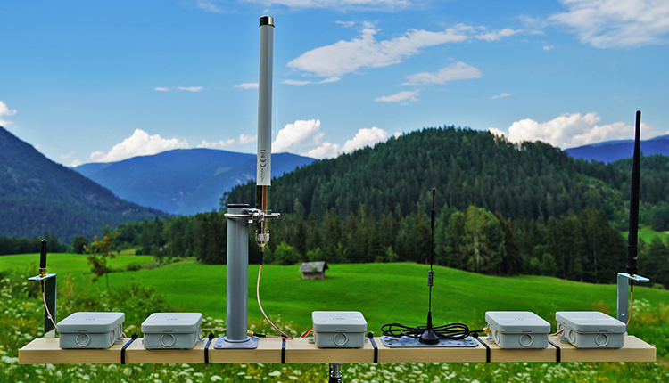
LoRa ist eine sehr beliebte Technologie für IoT und Mikrocontroller. In diesem Artikel geht es um die besten LoRa Antennen und den großen Reichweite Test
WeiterlesenAEQ-WEB © 2015-2026 All Right Reserved